Composite Propeller Fabrication
If it weren't for building this prop, I might not have started my other web pages. I started this web page with the intention of using it to help exchange information with another group of individuals interested in building props using the techniques described here. My web site has grown from this small section to include all the other web pages.
It all started when I posted a question regarding props on the Canard Aviator's Mailing List. Nigel Field responded and told me of a technique he used to make a composite prop from wood-fiberglass-epoxy that exceeded the performance of most commercially available props. That began an exchange of email where Nigel patiently explained all the steps and provided me with a sketch of the prop. The most amazing thing to me is it only cost about $70 in materials to make the prop compared to $1800 for a new 3-blade prop. Nigel ran the numbers for me on the PropOpt software from Bates Engineering and I used a CAD system to plot the airfoil sections and planform.
You can see the LongEZ prop data from the Bates program by clicking here: LongEZ 3-blade Prop Data.
Nigel also ran the numbers for the a 3-blade Cozy MKIV prop: Cozy MKIV 3-blade Prop Data
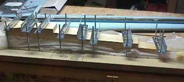
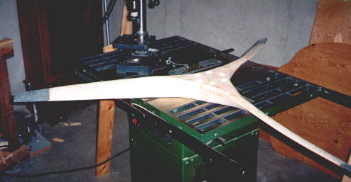
Shown above is a clamping fixture for gluing up the prop blade blank for carving. It is made of 2 sheets of particle board glued together to form the base. The clamps are made up of 7" long 1/4" carriage bolts and the hold-downs are perforated angle stock. I subsequently found it better to use 3/4" thick wood (prop wood material) for hold downs as it doesn't bend as much as the steel angle stock. It's also better to get some shorter carriage bolts for the thinner sections so you don't have to turn the nuts so much.
I also found that the wood glue I used in my practice blades had two shortcomings. The first was that it set up too fast which can make fine adjustments impossible if you don't get to them quickly enough. The second was that there were several areas in which the glue did not fill the gaps and produced voids. My next set of blades was glued up using wet flox ( a mixture of epoxy and milled cotton) which worked much better.
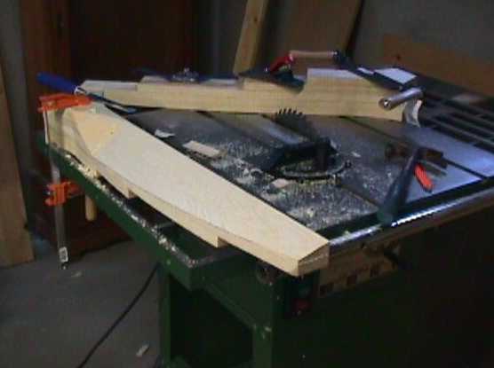
Shown in this photo is the bottom of the airfoil being shaped. Since the bottom of the airfoil is flat, it is made by successive saw cuts spaced about 3" apart. The wood is then removed with a chisel. The rest of the shaping is done with a spoke shave and belt sander.
The dashed lines on the drawing above show how the saw cuts are made on the blank. The blade is only shaped up to station 3 and then blended into the hub from there. When I cut my first blank I didn't make the cuts on the top of the airfoil because I hadn't gone through the drawings to make the measurements shown here. I ended up removing a lot of wood with the spokeshave which took a long time. After using the CAD system to measure the depth of the saw cuts, I was able to remove the majority of the wood above the cambered airfoil with the chisel which saved a lot of time on the other two blades.
Shown here is the cambered section of the blade up to station 3. We carved the cambered part of the blades with a CNC machine as that seemed to be the trickiest part of the airfoil to get right on my practice blades. The bottoms of the airfoil sections are flat and those are much easier to carve and adjust using simple hand tools. The CNC machine was a luxury for this kind of work and it did a great job at getting the cambered portion of the blades into perfect shape. Each blade took about 1.5 hours to carve on the CNC machine.
Here's a tip: It is very easy to get confused when carving a prop for a pusher aircraft and end up carving the blades backwards. (I know this from firsthand experience :-) On a conventional (tractor) airplane, you get used to seeing the cambered surface when looking into the prop. On a pusher, it's just the opposite. Failure to keep this straight in your mind will result in generating some 'practice' blades. Here's a mantra to recite: The flat part of the prop always faces the back of the plane. This is true for a pusher or tractor, regardless of the direction of rotation of the engine. Keep saying that to yourself over and over and you will avoid much unnecessary confusion. Of course, you must also be aware of the direction of rotation of the engine.
Here is a picture of the prop with the carbon tips and the holes drilled for the flox pads.
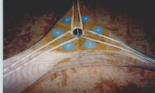
Here's a close up showing the flox pads, the aluminum insert, the moat, and the spar grooves cut into the wood. The 1/4" holes are the pilot holes which will eventually be opened up for the 3/8" prop bolts.
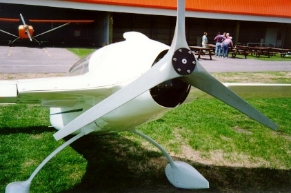
This is a finished example of the prop.
Nigel made a recommendation to add some 45 degree reinforcements on blades longer than the one I have described here to achieve greater torsional stiffness. While testing a 67" dia prop for a Velocity Elite, Nigel noticed some flutter at 2000 rpm and solved the problem with 2 UNI reinforcements at 45 degrees. I have also added 1 ply of BID over the full length of the blades to prevent this kind of problem from occurring on my prop. Nick Ugolini also thought that this was a good idea and has since added a torsional layup to his prop since it was more flexible in torsion than it needed to be.I have included a spreadsheet of the strength calculations in Excel format. It shows the tensile load strength safety factor greater than 5.
Return to Lee Devlin's Home Page