Printable Drill Chart Decimal Equivalent

Share

If you have a 115 piece drill set and have lost the chart that translates the diameter of the drills to a decimal equivalent based on the drill number, letter, or fractional size I have scanned mine, stitched it together and have it available as a jpg or pdf file. When I lost mine, I spent an inordinate amount of time with calipers searching for the right drill diameter. Now that I found it again, I keep it near the drill index and if I ever lose it again, I’ll know where to go to make a new copy of it.

The chart is a real time saver. If you click on the image below, you’ll get the full scale jpg image of it. From there you can right click and ‘Save As’ to have your own copy of the jpg file so that you can print it.

Drill Chart Decimal Equivalent Printable in jpg or pdf

I generally print it to fit to a single page, which shrinks it a little. If you prefer, you can print it full size from the pdf file and then cut and tape it together.

UPDATE: After looking at that image for a while, I decided the chart needed a ‘do over’ and so I put it in a spreadsheet and printed it as a PDF which makes it much more readable. Click on the image below for a PDF file suitable for printing on a single page.

Drill Chart Decimal Equivalent Printable in pdf

Using a Drill Press like a Lathe to make a Center Hole

Share

My friend was building a Stirling engine and when he found out that I owned a small lathe, he asked if I’d machine a piston and cylinder for him. Having some materials on hand like copper tubing for the cylinder and some solid aluminum rod for the piston, I agreed to make the parts. Another one of the parts he needed was a 7/16″ bolt with a hole drilled down the center of it. He had tried to make the hole with his drill press, but ran into a problem where the hole he drilled was not centered. This became apparent only after the hole was finished, of course, as it exited the far end of the bolt off center.

I had an idea about a procedure for drilling an accurate center hole in a cylindrical part with a drill press by first aligning a drill vice to hold a drill bit stationary while using the drill chuck to grip and spin the work piece. My drill’s chuck can hold a drill up to 1/2″ in diameter, which would be more than sufficient to grip a 7/16 bolt on its shank. I thought I’d run a quick experiment and document the procedure for anyone else who may want to try using a drill as a lathe for making a center hole in a cylindrical part.


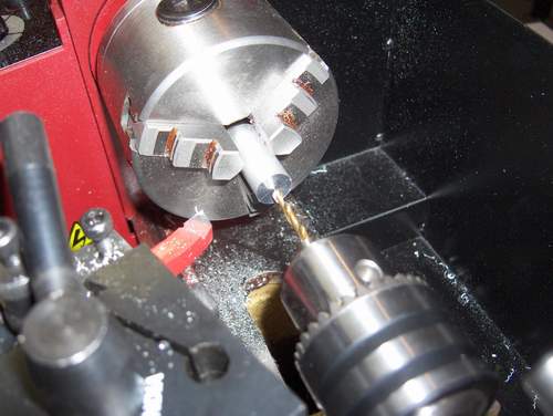
A lathe is most often used to turn a part using a cutter that can either remove material from the diameter or from the part’s face. But it also has a very nice feature when a drill chuck is inserted in the tailstock, and that is to accurately drill a hole precisely down the center of the part. An example of that is shown below.

Lathe with drill

Normally, you would use something called a center drill to start the hole and then swap it out for the drill of the proper diameter. If the hole is large, you may have to drill with several drill sizes to get it up to the finished diameter. In this case, the hole I wanted to make was just .125″ in diameter so it was possible to do with just a single drill in one step. The procedure I describe below would need to be modified by resetting the alignment for each drill if you need to open the hole up in several steps.

If you didn’t own a lathe but had a drill press and a drill vice, here is a procedure for drilling a center hole in a cylindrical part.

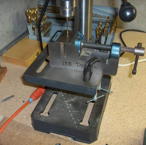
Aligning drill and drill and vice

First, you put a drill of the desired diameter in the drill chuck and tighten it. Then gently raise the drill table, clamp the table to set its height, and then and move the drill vise to the bit and clamp the drill vice down on the bit. The drill vice must have a ‘V’ groove one its jaws to align it vertically on the drill bit. This is important for a subsequent step. After everything is aligned, then use a pair of ‘C’ clamps to hold the drill vice to the table so it cannot slide from side-to-side. Then un-clamp the drill bit from the chuck and the drill vice and turn the bit upside down and clamp it in the vice’s V-groove again so that its tip is facing upward. Then clamp the workpiece in the drill chuck. In this case, I’m using a .5″ diameter section of aluminum rod as the workpiece.

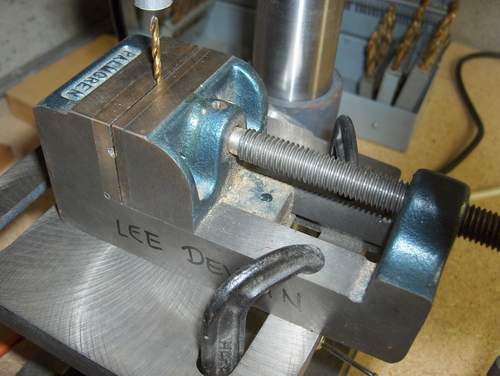
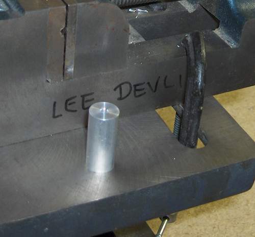
drill bit clamped into drill vice

Here the drill is clamped in the vice pointing upward and the workpiece is just partly visible and clamped into the drill’s chuck.

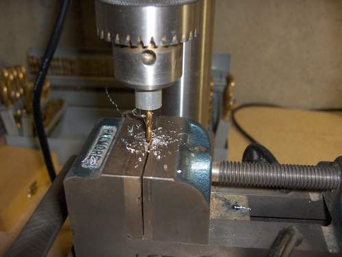
Then turn the drill on. Just like on the lathe, the drill bit will be stationary and you can lower the spindle with workpiece and it will drill the hole accurately through the center of the part. Remember to lift up on the spindle periodically to clear out the metal chips. If you got everything aligned correctly, the drill will make the hole directly in the part’s center. In my case, the hole was within .002″ of being concentric with the outside diameter of the part on both ends of the part. That’s about as accurate as you would get with a lathe so the technique works well.

Drill as lathe making chips

It may not be apparent but the part is spinning, the drill bit is stationary.

drill as lathe finished part

Here’s the finished part with the hole perfectly centered.

Fixing a broken latch on the Yaesu YSK-100 Separation Kit

Share

I’ve maintained the Yaesu FT100 FAQ for about 10 years. For those of you not familiar with ham radio, the FT100 is a popular mobile transceiver. I’ve talked to people from all over the world on it. As time went on, the FAQ stabilized and I rarely have to do much updating to it now other than to fix broken links. This FAQ still sees a fair amount of traffic.

My FT100 is mounted in my Durango using a YSK100 separation kit. The separation kit makes this radio easier to mount in a vehicle by separating the user controls, called the ‘head’, from larger body of the radio. The head then can be installed on a faceplate that is connected to the radio’s body with long cables. The body of the radio can be installed wherever you find room in the vehicle. Mine is hidden in the center console.

About a year ago, the latch that holds the head on to the face plate of the YSK-100 separation kit broke while I was removing the head.

I’ve never been happy with the YSK100 faceplate design since the latch requires an excessive amount of force to deflect when installing or removing the head. Without the latch, the radio could still be used, but it would fall off easily whenever I brushed against the head. Since the radio has been out of production for a few years, spare parts hare hard to find. So I decided to fix it myself.
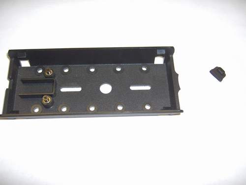
YSK-100 faceplate with broken latch

The plastic latch had cracked off of my faceplate.

There had been several reports of this problem on the FT100 Yahoo Group, but no one had ever reported figuring out a fix for it. You can’t just glue it back in place, because the part is highly stressed and a glue joint would not hold up to those extreme forces.
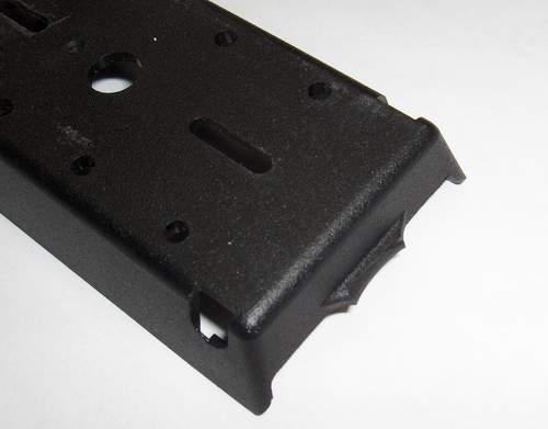
YSK with cracked latch

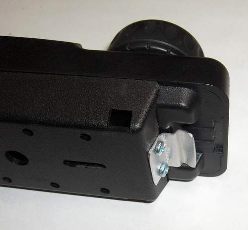
As you can see in the above image, a small portion of the latch is still on the wall of the faceplate. I sanded this off with a small belt sander. Next I took some measurements and started bending some .032″ thick aluminum sheet metal to make my own latch. I have a small metal brake/shear, but in this case, I just ended up using a vice to bend the sheet metal since the brake has a limit on how small the bends can be. I drilled some small holes and with attached it with M3 screws and nuts.
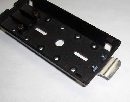
Sheet metal replacement latch for the YSK100

Here is a top view of the latch.

It works pretty much like the old latch in that it’s very stiff and holds with a lot of force. I suppose a thinner material, perhaps a lighter gauge steel, might have worked better, but this one can be bent to get the desired feel. If it ever breaks again, I know how to make a new one.
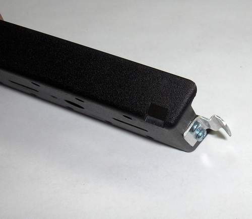
Here is a side view of the latch.
YSK-100 with metal latch

New metal latch with head installed.


Now that the radio is fixed, I plan to spend more time using it. When it was in that state of falling off the faceplate whenever I touched it, I frequently removed it all together and stowed it so it wouldn’t get damaged. But now I’m looking forward to having a properly functioning radio again. I tend to avoid using something that doesn’t work the way I want it to and then when I get around to fixing it, I wonder why I didn’t do it sooner.

I hope that others are able to take advantage of my description and pictures to help them to fabricate their own latch in the event that they break the plastic one that comes on the faceplate.

Finding the OBD port on a BMW E36

Share

A few weeks ago my wife’s 1997 BMW 328i illuminated the ‘check engine’ light and she called me asking if she should immediately take it to the dealer to see what was wrong. Since I had just changed the battery on the car and thus the electrical system had lost power a few times, I thought that it might be a false alarm and told her I’d like to look at the diagnostic trouble code (DTC) on its OBDII port before spending any money at the dealer. Taking a car to the dealer with a ‘check engine’ light is giving them permission to charge your for an hour’s labor for what might turn out to be nothing.

I had purchased an OBD scan tool at Amazon.com that hooks up to a USB port on a computer and it’s based on the ELM327 chip, which means it can read any of the standard protocols available on the OBD connector. However, when I first tried to use it on the BMW just to satisfy my curiosity after purchasing the tool, I recall not being able to locate the connector. On U.S.-made cars like my Dodge Durango, these OBD connectors are located under the driver’s side dash and are usually exposed and thus easy to locate. In looking through a few BMW forums for help on where the port is located, I found some conflicting advice about the port being under the hood and having a special round plug that was unique to BMW. Some forum responses assured me it was down there under the dash next to the clutch but it was covered.

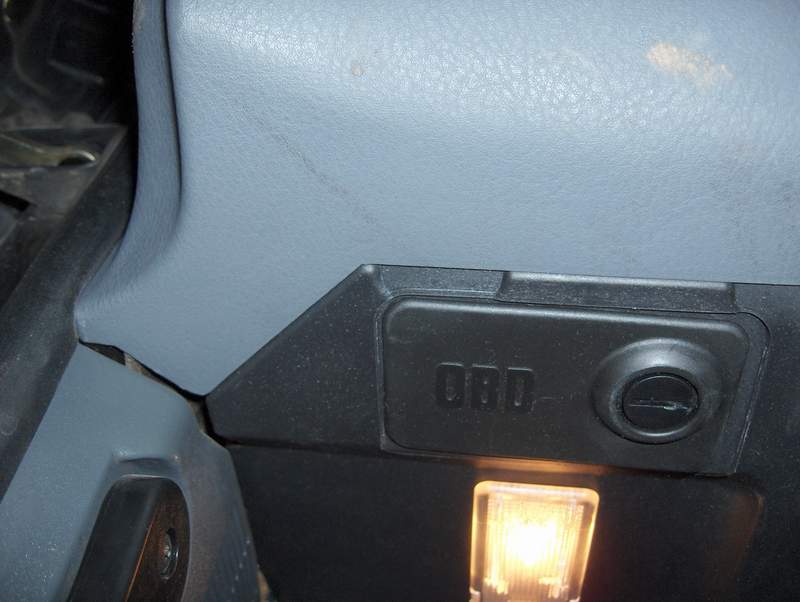
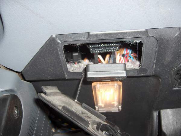
After getting a flash light and putting my head under the dash, it was almost embarrassing that I didn’t find it sooner. BMW put a cover on it that was clearly labeled OBD, but unless you’re a contortionist and get your head under the dash, you won’t be able to read that cover. The cover is easily opened by turning a screw head with a coin and the cover will hang down from a tether. Similarly, the connector itself has a cap over it which can be pulled off and it is also tethered. After pulling off these covers, the OBD plug was plainly visible.

Please note, the photos below are taken from the driver’s side floor looking up at the bottom of the dashboard.

BMW OBD port under dash

The BMW’s OBD port is covered

BMW OBD port opened

BMW OBD port shown with covers open

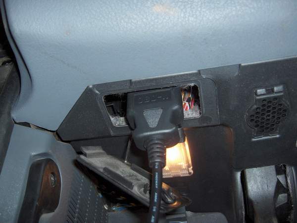
BMW port with cable attached

BMW OBD port with cable attached

After connecting the scan tool and running the software to check the codes, I found out the check engine light was complaining about a past event where the coolant sensor had reported too low a value. I checked the radiator fluid level and everything looked fine. I figured the car’s computer may have gotten confused when I was replacing the battery. I used the scan tool to turn off the check engine light. It’s been a few weeks and the light has stayed off, so the little device has paid for itself several times over just for that one usage.

I wanted to document this here in the blog in case someone goes searching for how to find the BMW’s OBDII port since a few pictures of it sure would have been helpful to me.