
One day I returned home only to find that our Sony Wega TV (Model KV34HS420) was no longer working. It would respond to the remote control and begin to start to turn on, but then it would make a clicking sound and turn itself off before a picture appeared on the screen. After that, the standby/timer LED would continue blinking 6 or 7 times. This blinking LED is a diagnostic code, but its description of the potential issue provided little value. After reading a few dozen postings on the issue, a pattern began to emerge that made me hopeful that I could repair it myself.
We purchased this TV in 2005 while the jury was still out about which flat panel TV technology would eventually replace the tried-and-true CRT technology. Back then, the LCD and plasma flat panel displays still had viewing angle and reliability issues and cost 2 or 3 times as much as an equivalent-sized CRT model and so we just decided to replace our 15-year-old Sony CRT TV with a modern HD-capable CRT TV. I was hoping to get 15 years or more out of this $1500 investment before having to send it to the landfill. After all, this was a SONY, not some no-name brand that I’d expect to fail after only a few years. And tube TVs usually last a very long time. I have one in my basement I purchased in 1985 that is still working fine.
This TV has excellent picture quality and no restrictions in viewing angle, and other than its size and weight, I found it much better than what was available with flat panel technologies at the time. Its speakers provide excellent sound quality, much nicer than the tinny sound produced by some of the razor-thin flat panels. It sits in a corner and therefore takes up no more room than an equivalent size flat panel display. So, after only 6 years, I was wondering whether it would need to be replaced or if I could fix it. After a fair amount of forum reading, I found that this 6 or 7 LED blink code was a rather common problem, along with a common solution, namely to replace the MCZ3001DB integrated circuits known as IC8002 and IC6501 on the ‘D’ board. This chip is functionally identical to earlier versions of it known as MCZ3001D or MCZ3001DA. The forums had many people describing their success at making the repair, but pictures of this procedure were non-existent, hence the reason for this blog posting. Also, the level of difficulty and amount of work involved was not clearly described, so I hope to explain and show what I did so the reader can determine whether it is within his or her skill level to attempt this repair.
This TV weighs 200 lbs. I didn’t want to have to move it from its stand. Fortunately, it was possible to remove the entire back shell simply by removing all of its screws and sliding it off. There are a lot of screws, about a dozen around the periphery of the TV along with several more on the back panel, but fortunately, it’s a one-person job although it wouldn’t hurt to have a helper because the shell, although fairly lightweight, is bulky. Removing the shell allows access to the ‘D’ board.

After removing about a 17 screws, the rear shell can be slipped off.
The ‘D’ board is the one shown in the picture below. I should mention that before removing the cover, you must unplug the TV and give it a few hours for the high voltages to dissipate so as to avoid shock hazards. It’s best to unplug it and wait overnight, since if the TV is not working so there’s no need for it to remain connected to power.

The 'D' board shown above is held in with about 8 screws.
It wasn’t clear how to remove the board, or if it would be necessary to undo all of the wiring connections. Some of the connectors were easy to remove, but the 3 high voltage wires that connect to the CRT did not have easy-to-unplug connections. I eventually figured out that I didn’t need to remove those wires at all. There are a number of connectors that need to be flipped upward to disconnect the ‘D’ board from an adjacent board. It wasn’t clear at first how they worked, but if you feel around for a flange you can pull them upward, they’ll unsnap and pivot up 90 degrees like a draw bridge. Two of the connectors had latches on them that require squeezing the lever to unlatch it before they will come out. I unplugged all the other cables I could find, removed about 8 screws, and the board came out far enough to let me rotate it into a position where I could access the bottom of the board. It was necessary to use a stubby screw driver to remove one screw that was far forward, hidden between two connectors, and just under the CRT. To make that easier, you will notice that there are two plastic hooks, one on each side of the tray that the boards are mounted to that you can unlatch which allows all the PC boards to slide back about 4 inches. That makes the front screw easier to access, although you’ll still need that stubby screwdriver. (I’ve since added images of the latch and the board slid back at the end of this article.) After you get all the screws out, the board is still held in by a few plastic clamps on the edge which you can bend back a little to release the board. The board was still tethered by the high voltage connections, but I was able to fix it ‘in place’, by turning it over like shown in the image below.

Bottom of Sony 'D' board shown rotated in repair position. Note, it's not necessary to disconnect the wire with the suction-cup-like insulator on it.
Unsoldering the two ICs is not difficult if you use a spring loaded solder sucker like the one shown below. Do not waste your time trying to use solder wick or a bulb-type solder sucker for desoldering the chips. Search for YouTube videos with the word ‘desoldering’ if you’ve never desoldered a chip before to see how it works. Also, make sure that the soldering iron is a low-wattage type, and not too hot to avoid lifting the copper traces.

A spring loaded solder pump/sucker like this one works best to remove the solder.

Close up of IC6501 and IC8002 from bottom of board. Note each IC has two unsoldered pins.

Do NOT solder pins 13 or 17. If you're using a socket, it would be best to clip the legs in those holes off the socket.
Be aware that each chip has two pins are not soldered to the board. This is normal and so don’t try to solder those pins or the fix will not work. Take note of the orientation of the chips since there is a notch on one end facing the closest edge of the board. You do NOT want to install the chips backwards. Also, don’t solder the new chips in directly to the board. Use sockets in case you ever need to do this repair again, since having to unsolder these chips is most of the work. If they were socketed in the first place, you could replace them without having to solder or even having to remove the D board.
I wasn’t sure of the best way to purchase the ICs, since forum participants mentioned purchasing them on Ebay, where there are several China-based vendors offering MCZ3001DB chips but the shipping times from China vary considerably and can take from 10 days to 3 weeks. The vendor I chose was TriState Module because I wanted a U.S.-based company. They sent me a pair of ICs for around $20 including shipping charges. However, they no longer have these parts in stock and they are getting harder to find. I also needed a pair of 18-pin dip sockets which I found at the local Radio Shack for $.59 each. They look like the parts on the left in the image below:

After replacing the ICs with sockets, you’ll need to install the replacement ICs. Odds are that only one of the chips is bad, but since you won’t know which one, it’s best to just replace them both. It is necessary to squeeze the pins together to get the legs aligned with the holes in the sockets. This style of IC has its legs spread out by default, and so they won’t automatically align unless you pre-bend them inward just a little to align with the holes in the socket. Carefully examine the chips after you install them to make sure all the legs made it into the socket and that the little half-circle notch at the end of the chip is facing toward the near edge of the board as shown in the photo below.

IC8002 and IC6501 installed in their new sockets.
After re-installing the board and attaching all the cables, it would be a good idea to test it to make sure the repair worked before reinstalling the cover. If you unlatched the tray and slid the boards back to make access easier, you’ll need to put them back in position or else the remote control and on/off button won’t reach the board. With luck, your TV will be back up and running, avoiding a premature trip to the landfill. I can’t guarantee this fix will work for you, but the consensus on the forums is that it frequently fixes the 6 or 7 blink code problems on the Sony Wega flat screen CRT models.
I found the repair to be of intermediate difficulty, and the result was very gratifying when the TV turned on again. Our TV has now been working like new for more than 2 years, and if it ever happens again, I could fix it more easily thanks to the sockets that are installed. It felt good to resurrect a TV that has great picture and sound quality and, hopefully, a lot of life left in it.
And, in the event it doesn’t work for you, then maybe getting one of those new and improved flat panel TVs is your best alternative. 🙂
[UPDATE 2013-11-15] I mentioned earlier about the difficulty of finding and removing one of the screws under the CRT. Some of these TVs, including the model I repaired, have a set of latches that allow you to release the board and carrier and slide it back about 4″ to make that screw much easier to access. You can see it in the images below:
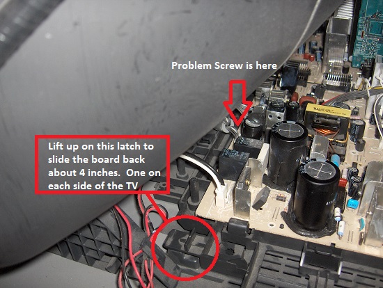
The D-board and its carrier have latches on both sides that can be lifted to slide the assembly backward about 4 inches.
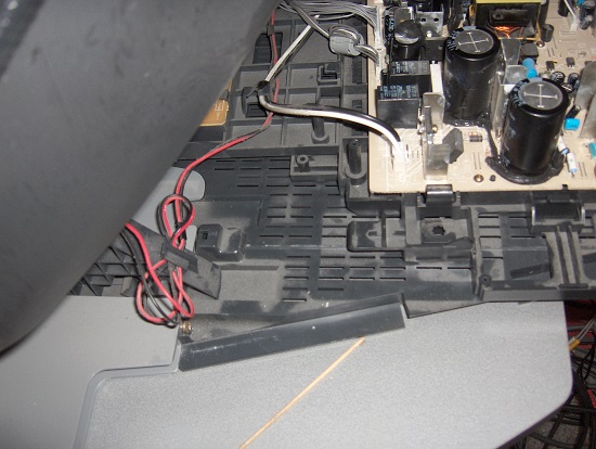
D-board slid back 4″ into the repair position.
Lee, A note of thanks, yes another success story on saving my great TV. also saving big bucks. All worked out just as you said and with all posts helped my decision to try it myself. thanks again. ralph
Lee,
Had the 7 blink code problem a few months ago, researched it, found your fix, ordered the parts… but in the mean time found that if I unplugged the set and let it cool, in the morning it would power up normally. The blink codes seemed to occur when the set was hot, was turned off and then turned on again in a short period of time. So the obvious solution was to leave it on. It was working, and installing the new chips seemed to have about a 1 in 10 chance of bricking it. After around 3 months, it finally failed in service with the same 7 blink code. The good news was installing the new chips/sockets (Once I figured out where I stashed them months ago) did indeed fix the problem!
Thank you for taking the time to publish and update this fix.
Lee, A short note of thanks for your detailed instructions on the repair of the Sony TV with the 6 blinking lights. About a month ago, my kids were watching our Sony when the picture went blank and the dreaded flashing began. I had experienced a similar issue with my in-laws TV and it had resulted in an expensive repair as the Power Supply module had to be replaced. Fearing the worst I turned to the internet and located your site. I had never done anything close to soldering, let alone opened up a TV and expected to come out alive. With the cost being so minimal and the worse possible outcome being that I would have a TV that still did not work, I ordered the parts. I found a spot in Indiana (Fushicho Trading Co, LTD, Whitestown, IN 46075) that had the chips and the sockets. I proceeded to disassemble the TV. The screws around the TV were not bad and I found that by lifting the tray that held the board, even the hidden screw could be easily accessed. I tipped the board up and began to use the iron and solder weave tape to remove the solder from the existing chips. The removal probably took me an hour as I was very nervous about getting all of the solder off the board. I then took the sockets and clipped the legs that were not to be included. I soldered the new seats in place. I inserted the chips and powered her up. Unfortunately, the light pattern was now 3 rather than 6. My worse fears had been realized.
The following week, a friend in the electronics trade was in town and I explained to him what I was doing. His first question “So you have never soldered before and your first project was your TV?” We laughed a bit and he agreed to come over and take a look see at my handy work. His first comment was “So you are from the school of more solder is better, eh?” I had some cold solder joints and more solder than was necessary to do the job. He said though that the real problem in these types of repairs is that too much heat is applied during the removal process and you break a connection on the board called a trace. These are fine layers of copper that can be pulled loose during this kind of work. He examined the board and found a broken trace. Using some fine wire and solder, he replaced the trace on the board. He cleaned the board up and removed any excess solder from my connections. I put the TV set back together and fired it up. There she was, as good as new!
It was quite an experience but has continued to work for a week now so I am confident the fix was a good one. I also now have the sockets so that when these chips go bad, they can just be popped out and replaced.
I would recommend the experience to anyone. It was scary and exhilarating all at the same time. I was so happy to see the set working again! Thank you so much for all the detail you provided as it made this all possible.
-Greg